Sheet metal machines category would be hard to imagine without one of its pillars – press brakes CNC/NC. Despite the fact that today a huge number of different press brakes machines are used, they all have similar components.
We will consider both the most necessary ones and those that appeared as the result of the desire of the equipment manufacturers to improve their product and, in fact, the technology of bending on Press Brake machines.
Each machine, despite the manufacturer and brand name consists of a bed, a movable and a fixed beam, a drive of a movable beam and an attachment system for the tool. Already at this point, there are obvious differences between existing designs.
In addition, modern press brake machines have a system of rear stops, compensation of deflection, other auxiliary features, and devices. All this is controlled by the CNC, which can perform other useful functions.
Press Brakes Components
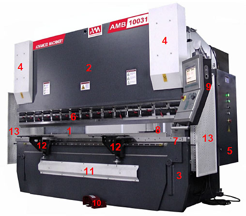
- 1) Stand
- 2) Upper (movable) beam
- 3) Lower (fixed beam)
- 4) Hydraulic cylinders of the upper beam drive (under the covers)
- 5) Electrical cabinet
- 6) Punch fastening system
- 7) Matrix Mounting System
- 8) Rear stops
- 9) CNC control panel
- 10) Control pedal
- 11) The bombing system (under the casing)
- 12) Front sheet supports
- 13) Protective fences
Press Brakes Construction. Stand Frame.
In general, two types of press brakes bed frames are used. Some machines are equipped with a C-shaped frame and other press brakes have an O-shaped frame. Let’s closer inspect the advantages and disadvantages of each frame type.
C-frame type press brakes
The c-shaped frame is the most common for press brakes. The name of the frame comes from the shape of the left and right sides of the machine, having an opening for the parts and installing the tool.
This opening is often called a yawn, and the geometric dimensions of the opening are the depth and height of the so-called neck. Movable and fixed beams are installed on the frame in front so that the distance between the sidewalls is less than the length of the beams defining both the maximum length of the bend and the main width of the machine along the width.
The c-frame design has a number of advantages:
- The width of the machine is narrower in width (as a rule, equal to the length of the bend or slightly exceeding it);
- more space for installing large and heavy tools on the side;
- the possibility of extracting complex details from the side;
- The possibility of using several machines in a pair for the bending of very long parts. This design is often called “Tandem”.
The disadvantages of C-frame configurations are:
limited space with a yawn while bending details of the maximum length – they can rest against the sidewalls;
at high loads, the frame begins to “open” so that a displacement appears not only in the vertical plane, but also in the horizontal plane.
As a result, the relative position of the punch and the matrix changes – their working axes do not coincide.
O-Frame Press Brake Machine
The O-frame also consists of two sidewalls, but here they are much smaller and located on the sides of the working beams. Each sidewall has only a non-verbal hole for mounting the tool. Accordingly, all the distinctive features of the C-frame are copied “exactly the opposite”
Disadvantages:
other things being equal, a larger overall width;
a limited opening for the installation of the tool from the side; therefore, the fastening system is most often used, allowing the tool to be installed from below and from above;
It is impossible to extract complex details from the side;
It is impossible to combine machines into a tandem.
Benefits:
sidewalls do not restrict complex details over the entire length of the bend;
load on the bearing sidewalls is distributed evenly and small deviations in the geometry occur only in the vertical plane. This makes the bending more accurate and predictable.
There are also machines with a lower movable beam. In this embodiment, the entire beam drive system is located at the bottom of the machine, which simplifies the design and maintenance. The center of gravity is much lower, so the machine is more stable.
The main disadvantage is manifested in the daily use of the machine. The punch always remains motionless, and the matrix rises at each bend. Together with it, the rear stop should be raised, and most importantly, the operator must also raise the workpiece.
In the vast majority of modern machines, the lower beam is fixed and is part of the frame. The entire drive system of the upper beam is located on top of the machine. This scheme is much more convenient for the operator, and modern design solutions allow it to be implemented.
Thank you for reading our articles, stay informed about the industrial world and Exapro by following us on Exapro Hub, Facebook, Twitter, and LinkedIn.